
 EN
EN
 ar
ar bg
bg hr
hr cs
cs da
da nl
nl fi
fi fr
fr de
de el
el hi
hi it
it ko
ko no
no pl
pl pt
pt ro
ro ru
ru es
es sv
sv tl
tl iw
iw id
id lv
lv lt
lt sr
sr sk
sk sl
sl uk
uk vi
vi et
et hu
hu th
th tr
tr fa
fa ms
ms hy
hy ka
ka ur
ur bn
bn mn
mn ta
ta kk
kk uz
uz ku
ku
Differential Water Level Gauge
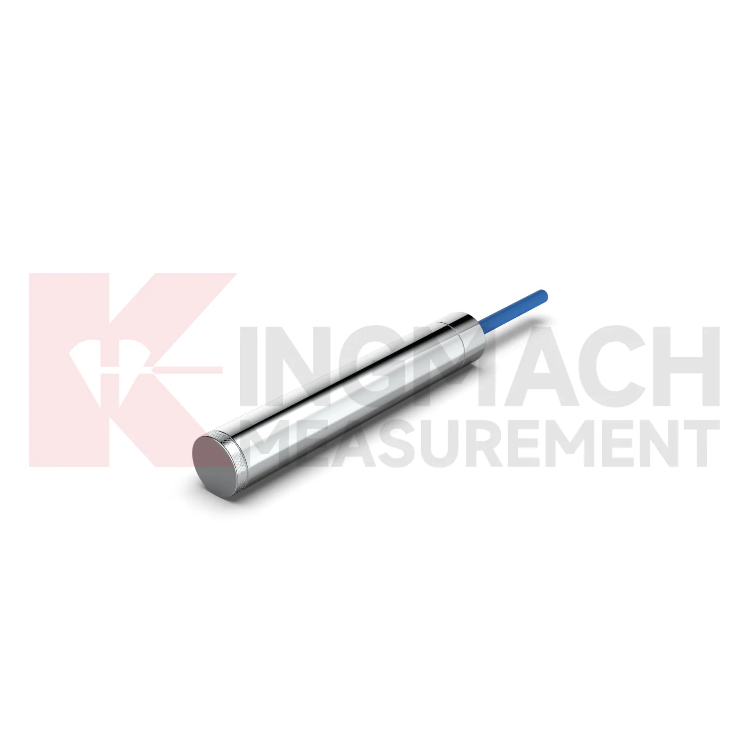
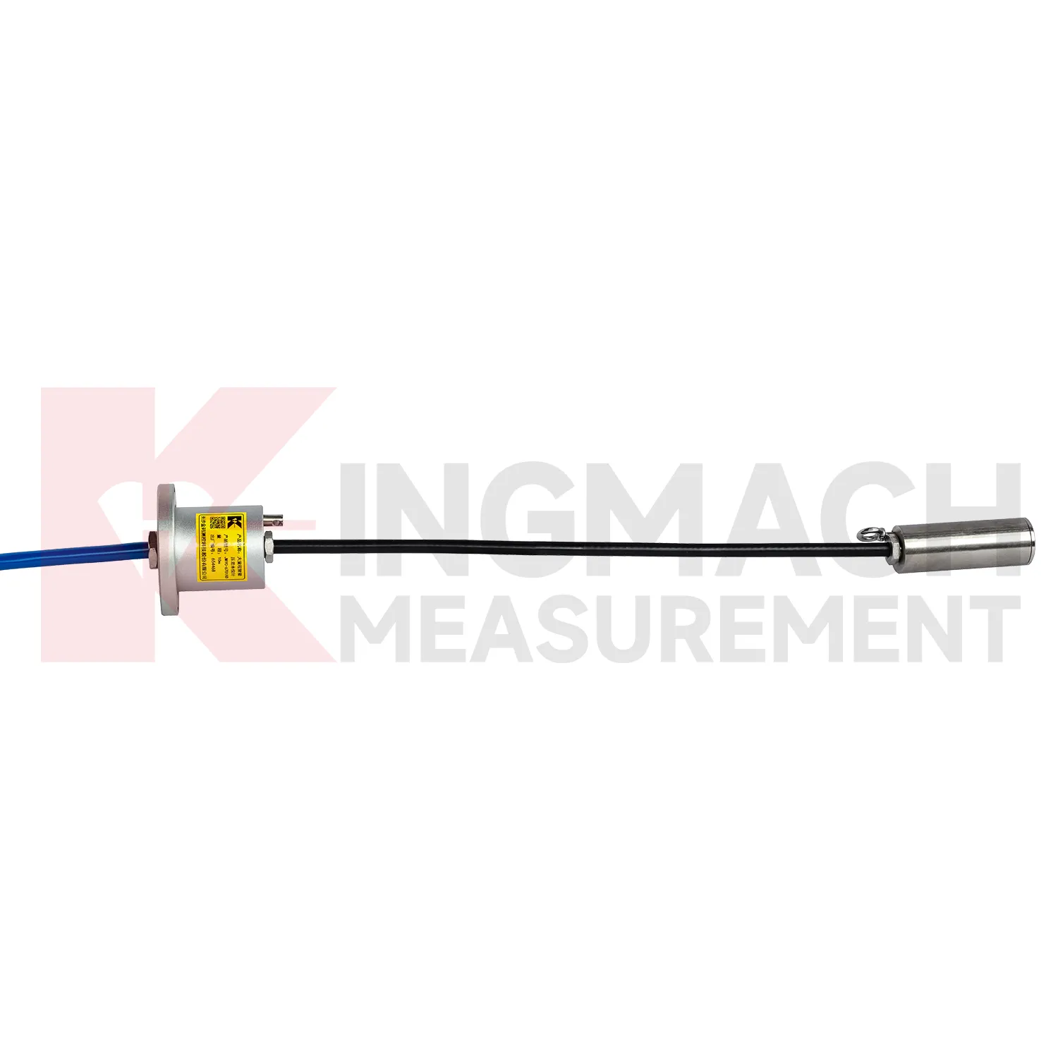
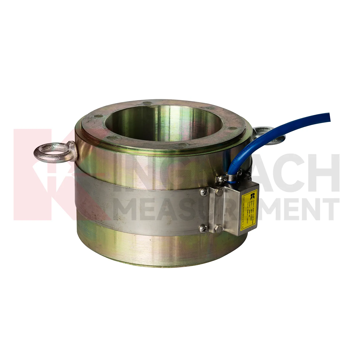
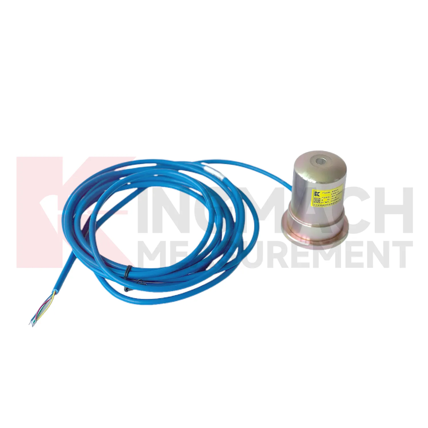
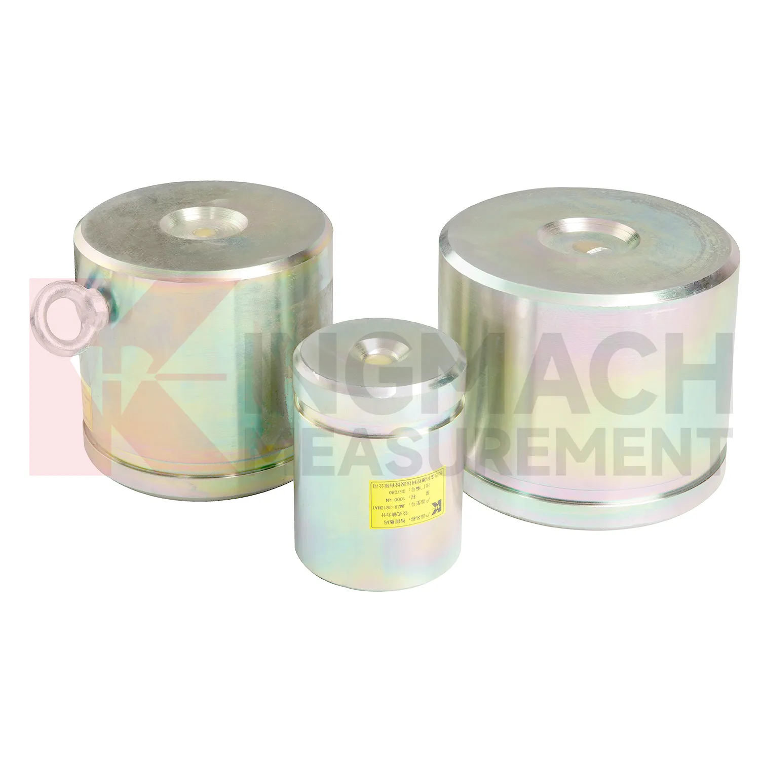
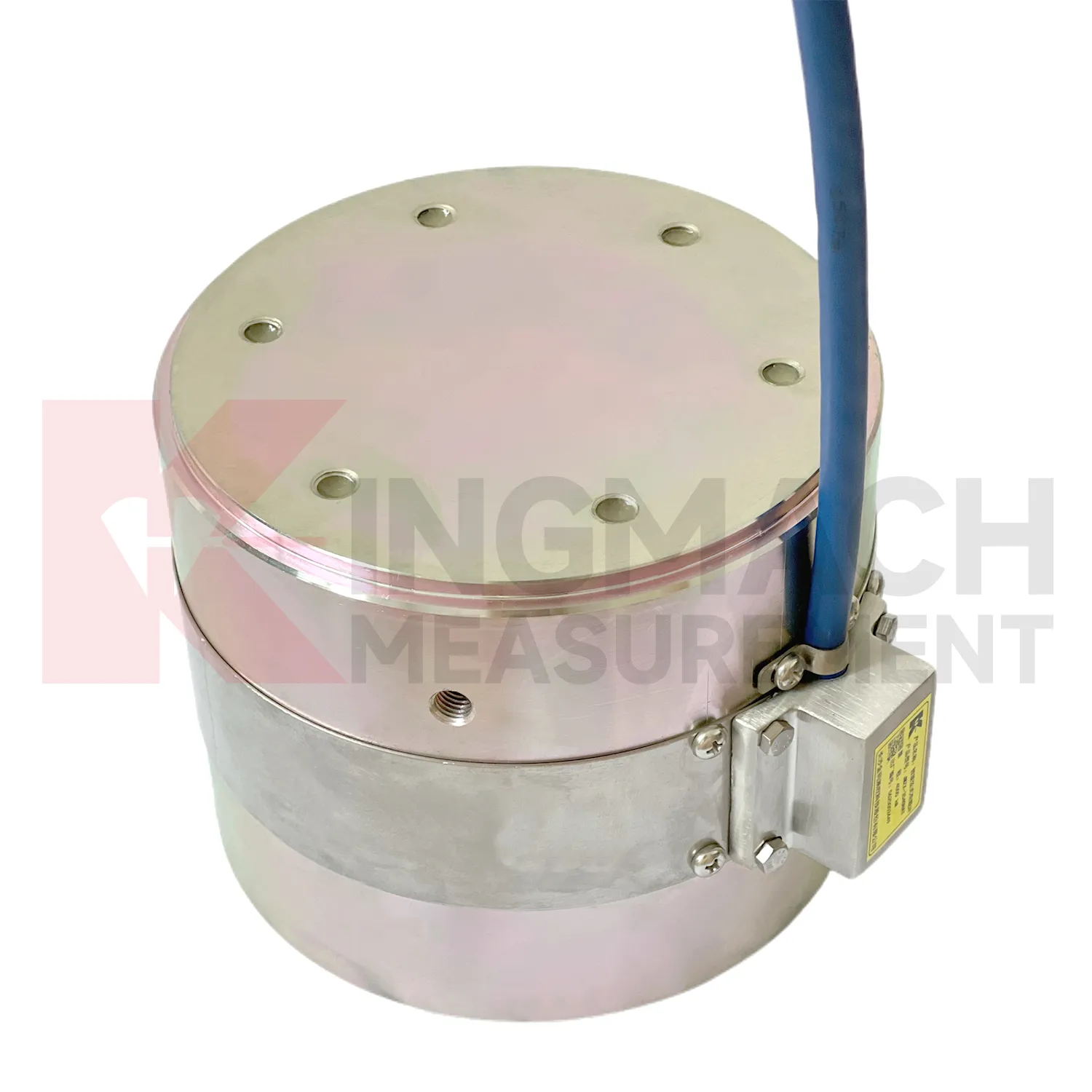
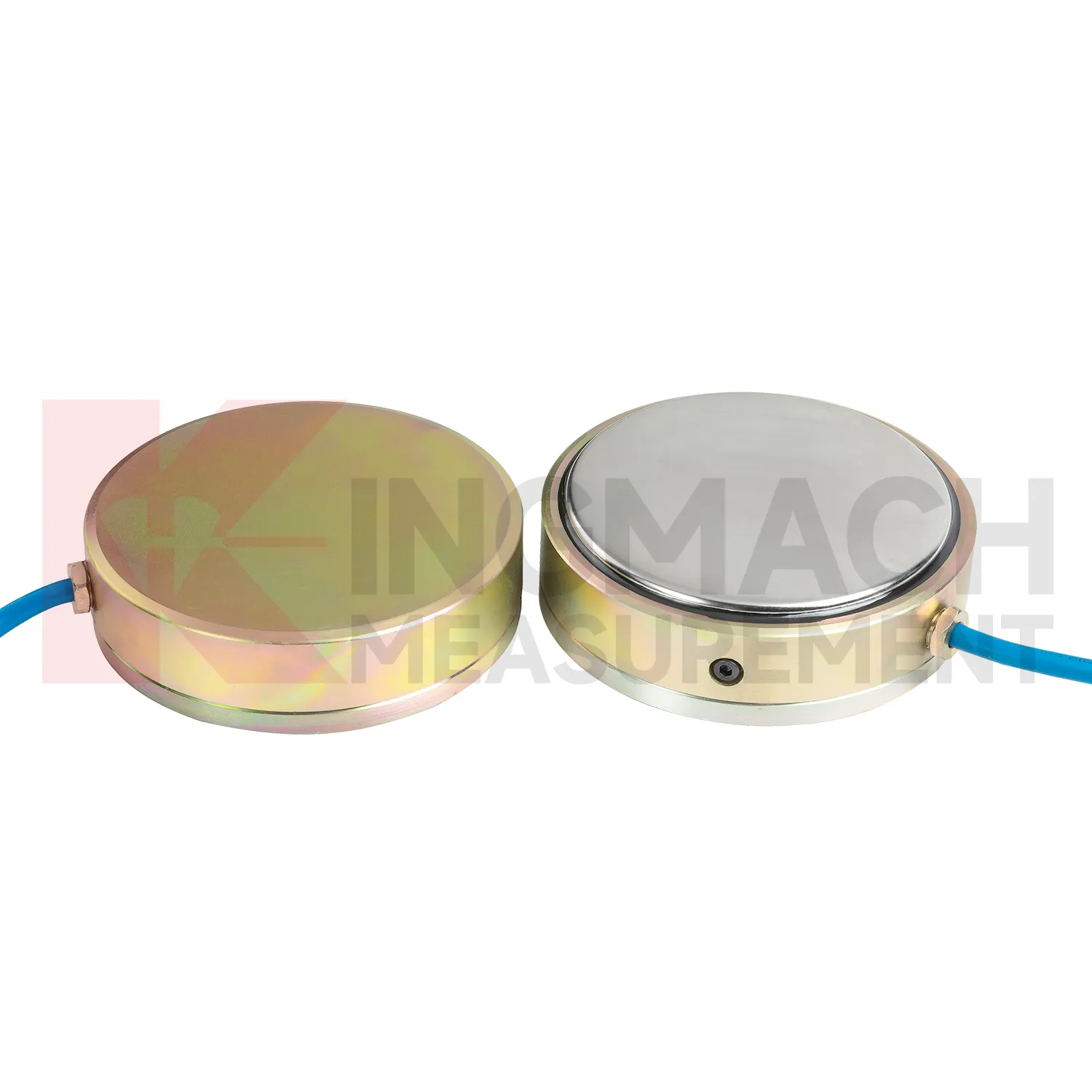
Kingmach Differential Water Level Gauge products are built for projects that need force data with a clear technical trail. The hollow load cell JMZX-3XXXHAT uses an annular multi-string elastic steel structure and is listed from 500 kN to 8000 kN, with 0.1 kN sensitivity on the 500 kN model and 1 kN sensitivity on larger models. Its product file also lists a 50 year design life, digital output, automatic temperature correction, waterproof durability, and storage for 800 measurement records. Those details are relevant in bridge cable force monitoring, anchor testing, and long term structural health monitoring, where the same point may be checked for many years. Kingmach, based in Changsha, supplies sensors with readouts, data loggers, DTUs, and software platforms, so the measuring point can be connected to a wider monitoring network. For a project team, the important value is not a catalog claim. It is the ability to identify the sensor, read the same force channel consistently, compensate temperature influence, and keep a documented record when access becomes difficult after construction. For brand context, Kingmach Measurement & Monitoring Technology Co., Ltd. works from Changsha, Hunan, and its product pages group load sensing with structural health monitoring, engineering monitoring sensors, readouts, data loggers, instrumentation cables, and visualization software. That catalog context matters because a force sensor is often purchased with the equipment needed to read and archive it.
Application of Differential Water Level Gauge
In dam and hydropower monitoring, Differential Water Level Gauge can be used for anchor force, concrete bearing pressure, gate structure load checks, earth pressure near embankments, and long term load review around seepage control areas. The monitoring difficulty is durability. Access may be limited, water influence is persistent, and seasonal temperature changes can mask small force trends. Kingmach hollow load cells list a 50 year design life, waterproof durability, automatic temperature correction, digital output, and 800 stored measurement records. Earth pressure cells also list a 50 year design life, 0.5%FS pressure accuracy, and ±0.5°C temperature accuracy. These parameters support long observation periods, especially when readings are tied to reservoir level, seepage, rainfall, and temperature records. For dam owners, a single force value is rarely enough. The trend should show whether anchors remain stable, whether pressure increases after impoundment, and whether unusual readings appear near maintenance or water level changes. Automated acquisition is often worth planning where manual access is costly. For long service assets, the monitoring plan should also say who checks the reading after storms, earthquakes, reservoir level changes, or maintenance work. A sensor that is never reviewed at the right moment does not give the owner much protection.
The future of Differential Water Level Gauge
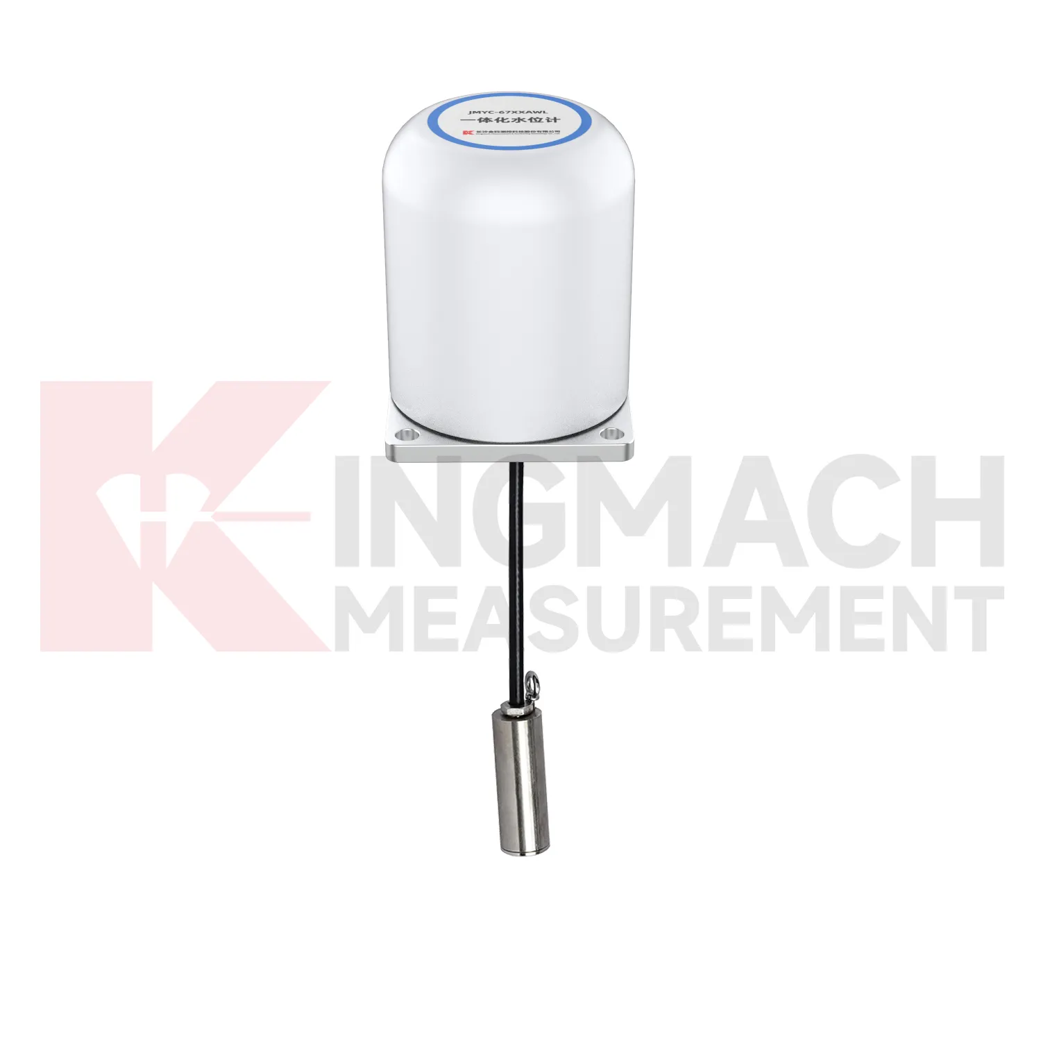
The next stage for Differential Water Level Gauge in infrastructure monitoring is tighter integration with site data systems. Smart sensors already store model data, calibration coefficients, zero values, temperature readings, and measurement records on selected Kingmach products. The practical path is to connect that identity data with 4G, LoRa, wired acquisition, or 5G gateways, then place the force trend beside displacement, settlement, pore pressure, and rainfall in the same review screen. This matters because future warnings will be less about one limit value and more about patterns: force rising after excavation, anchor load falling after heavy rain, or bridge cable force drifting during seasonal temperature cycles. Digital twin models can use those readings when the sensor location, range, and calibration background are reliable. Standards and owner specifications for structural health monitoring are also becoming more data traceability focused, which favors instruments that can carry their own calibration identity and remain readable through long service periods.
Care & Maintenance of Differential Water Level Gauge
For Differential Water Level Gauge working in cold, hot, or wet environments, maintenance should use the product parameters as inspection triggers. Solid load cells list a -30°C to 80°C temperature range, while axial force meters list 1 MPa waterproof performance and earth pressure cells list ±0.5°C temperature accuracy. These ratings help, but field practice still matters. During installation, keep connectors dry, avoid sharp cable bends, prevent direct mechanical blows, and secure the instrument away from water pooling where possible. During long term use, inspect after freeze-thaw cycles, heat waves, storms, flooding, and nearby welding or electrical work. Temperature correction should reduce measurement influence, but readings should still be reviewed with the actual site temperature. If a value moves only during daily temperature swings, check the thermal pattern before issuing a structural warning. If a value changes after water exposure, inspect sealing and cable insulation before resetting alarm thresholds. Do not ignore seasonal effects.
Kingmach Differential Water Level Gauge
Differential Water Level Gauge is not limited to weighing or lab testing. In Kingmach's project world, it is part of structural and geotechnical monitoring, where the object being measured may be a cable, a pier support, a pile, a retaining wall, a tunnel support, or a dam anchor. The instrument must survive rough installation and still return a clear force or pressure value. Capacity, sensitivity, accuracy, overload allowance, waterproofing, and temperature behavior all affect whether the data can be trusted months later. A sensor with the wrong range may flatten important changes or overload during construction. A sensor with poor protection may drift after water enters a connector. A sensor with unclear calibration records may create doubt during acceptance. The better approach is to match the instrument to the loading path and the reading method at the same time. That keeps procurement, installation, and data review working from the same assumptions. Those details keep the instrument useful after the original installation crew has left the site.
FAQ
Q: When is a solid Differential Water Level Gauge more suitable than a hollow type? A: Solid models are commonly used for compression load, pile load testing, bridge pier support checks, and heavy bearing capacity measurement. Q: What specifications does the Kingmach solid load cell list? A: The JMZX-35XXHAT line lists 1000 kN to 10000 kN ranges, 0.1 kN resolution, 0.5%FS precision, and -30°C to 80°C working temperature. Q: How much overload margin is listed? A: Product information lists 20 to 50%F.S. range overload and 300 to 400%F.S. failure overload. Q: What installation errors affect accuracy? A: Eccentric loading, uneven bearing plates, side load, cable pulling, and missing zero records can all distort results. Q: What records should be kept for acceptance? A: Keep calibration coefficient, model, serial identity, load stages, temperature, zero value, and readout setting.
Reviews
Michael Anderson
The strain gauges and load cells are extremely accurate and stable. They performed very well in our bridge monitoring project. Highly recommended!
Christopher Martinez
Very satisfied with the readouts & data loggers. User-friendly interface and supports multiple sensor inputs.
Latest Inquiries
To protect the privacy of our buyers, only public service email domains like Gmail, Yahoo, and MSN will be displayed. Additionally, only a limited portion of the inquiry content will be shown.
Emma***@gmail.comCanada
Dear Sir/Madam, we are interested in displacement transducers and settlement sensors for a geotechni...
Harper***@gmail.comIndia
Dear Sir, we are planning to procure a complete monitoring system including strain gauges, tiltmeter...
Related product categories
- calibration of load cell theory
- load cell failure
- load cell technology
- strain gauge load cell wiring
- diagram 4 wire load cell wire connection
- load cell accuracy calculation
- load cell amplifier circuit
- load cell calibration procedure
- load cell excitation voltage
- load cell unit of measurement
- mounting load cells
- strain gauge with load cell